Very Large Scale Integration: Take your career to the next level with our advanced training program
1st Feb 2026
Batch Starts
2 Months
Duration
5 Seats Left
Seats Available
4.5 
Program Rating
Overview
Program highlight
Empower Your Career with Our Complete, Industry-Focused Program
Designed for college students, Professionals, and Innovators Across All Fields.
Master Industry-Standard Skills with Certified Programs by Wipro.
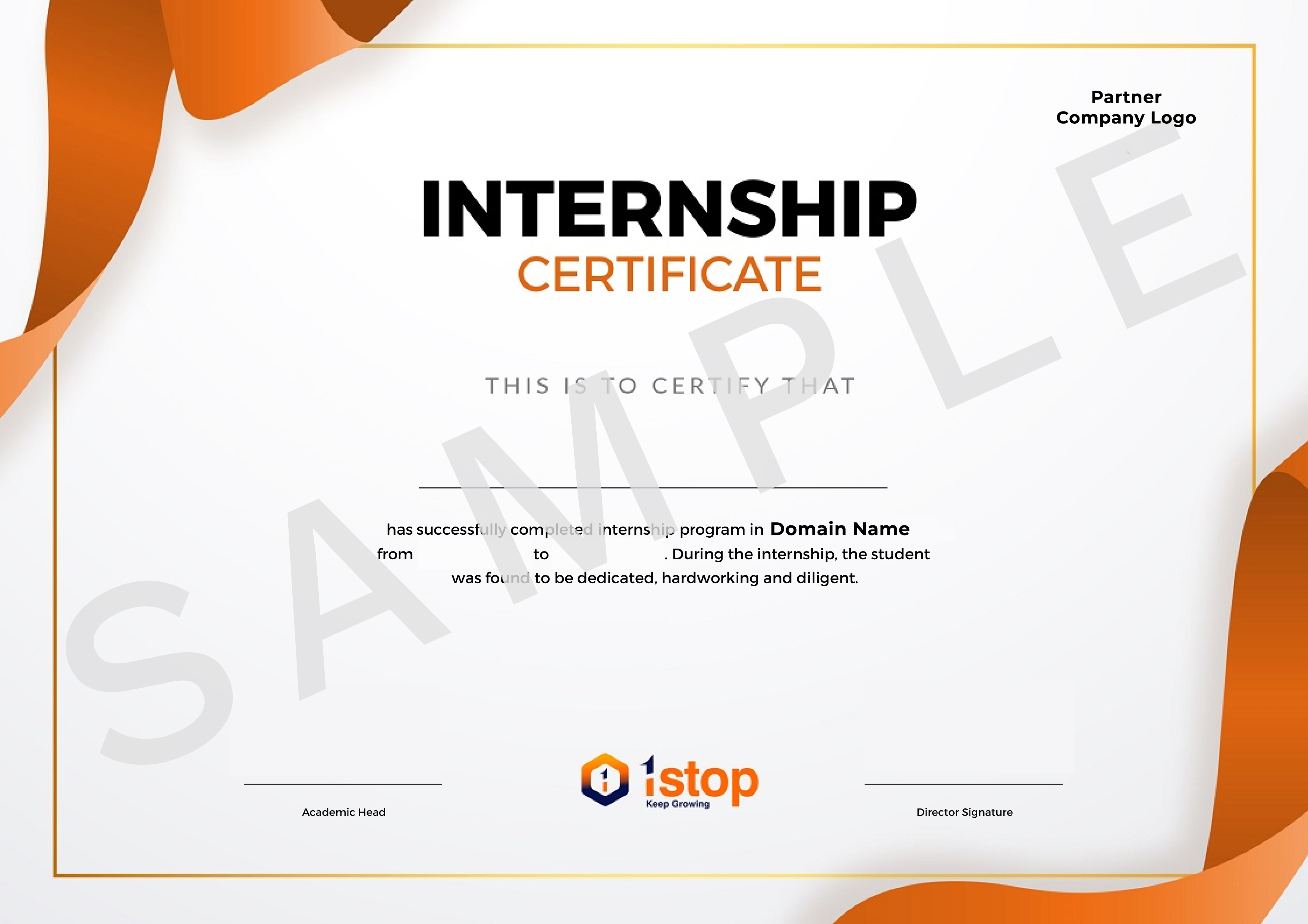
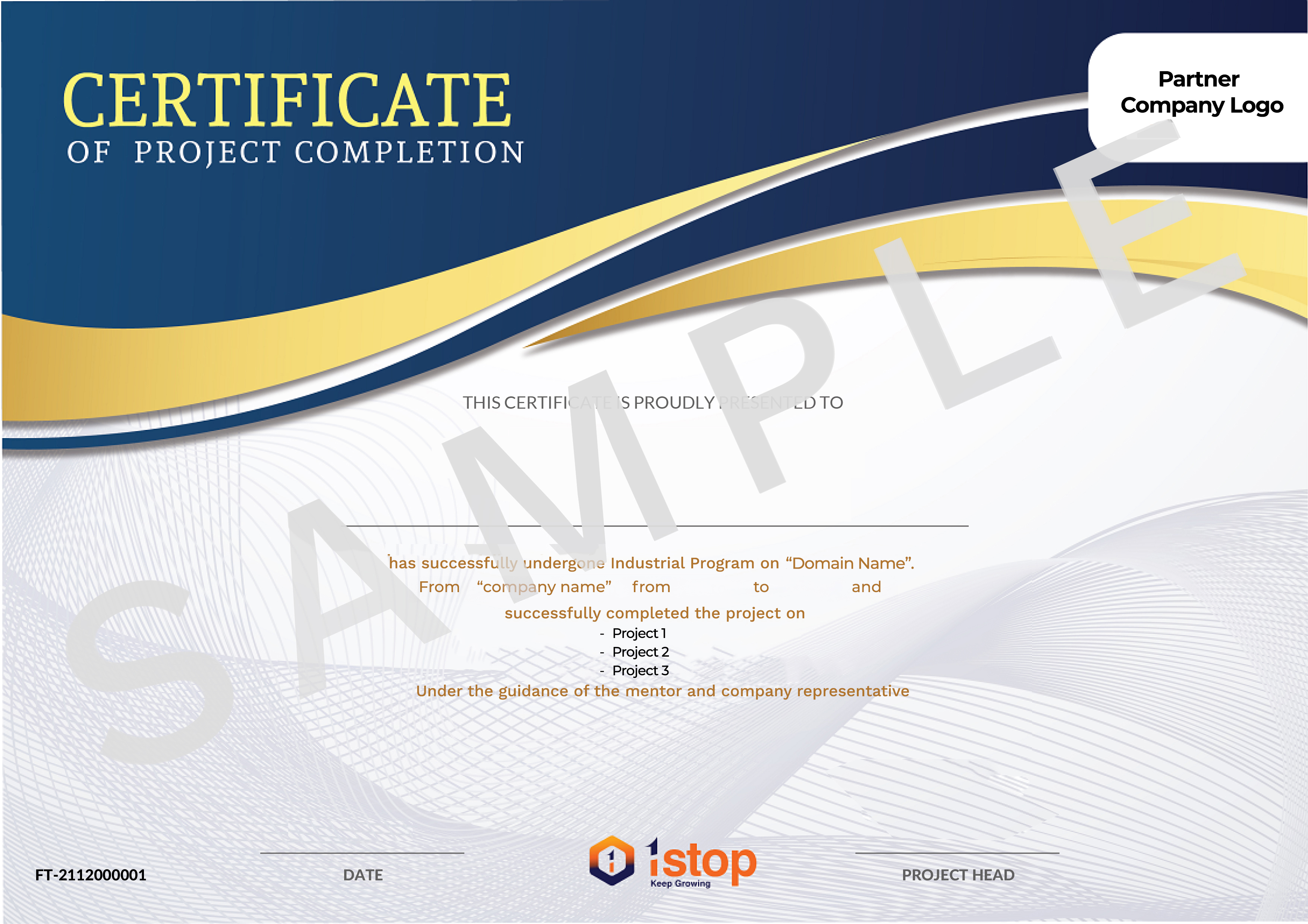
Earn certificates for your internship and program achievements.
Create a standout job-ready profile with an impressive project portfolio.
Here's Why You Need To Master This Program

50K +
Job Openings
$267 billion
Global Market Size
₹ 7.5 lakh
Average Annual Salary
- Overview
- VLSI (Very-Large-Scale Integration) is the process of creating integrated circuits by combining thousands to millions of transistors on a single chip.
- This allows for complex and powerful electronic circuits to be miniaturized.
- VLSI is widely used in processors, memory chips, and advanced digital devices.
- Evolution of VLSI
- First Functioning Point Contact Transistor was built in the year 1947
- Metal Oxide Semiconductor Field Effective Transistor (MOSFET) was built in the year 1959
- SSI: Small-Scale Integration with a few transistors per chip.
- MSI: Medium-Scale Integration, increasing to hundreds of transistors
- LSI: Large-Scale Integration, reaching thousands of transistors per chip.
- VLSI: Very-Large-Scale Integration, with millions of transistors on one chip.
- VLSI Design Flow
- System Specification
- Architectural Design
- Functional Design
- Logic Design
- Ciruit Design
- Physical Design
- Fabrication
- Packaging & Testing
- Digital Design
- Digital design involves creating circuits that process digital signals.
- It uses binary logic (0s and 1s) for computations and data handling.
- Common elements include logic gates, flip-flops, and registers.
- Digital design is foundational for computers, processors, and digital devices.
- Digital System
- A digital system processes and stores information in binary format.
- It consists of components like logic gates, memory units, and processors.
- Digital systems are reliable, precise, and programmable.
- Examples include computers, calculators, and digital communication devices.
- Number System
- Binary Number System
- Decimal Number System
- Octal Number Syste
- Hexadecimal Number Syste
- Number Base Conversion
- Any to Binay (Positional Power)
- Decmal to Any (Using LCM)
- Grouping (Binary to Octal or Hexadecimal)
- Binary Addition & Subtraction
- Binary addition involves adding bits and carrying over when the sum exceeds 1 (1+1 = 10).
- Binary subtraction requires borrowing when subtracting 1 from 0 (1-0 = 1, 0-1 = borrow).
- 1’s complement is used by inverting bits to perform subtraction.
- 2’s complement involves inverting bits and adding 1 for subtracting signed numbers.
- Overview
- Digital Signals: High Level = +5v, Low Level - 0v
- Positive Logic: High = 1/True, Low = 0/False
- Negetive Logic: High = 0/False, Low = 1/True
- Boolean Algebra
- Identities: Identity Law, Null Law, Complement Law, Idempotent Law, Domination Law
- Properties: Commutative Property, Associative Property, Distributive Property, Complementary Property, Idempotency Property, Absorption Property
- Logic Gates
- Logic gates perform basic operations on binary inputs (0s and 1s).
- AND: Outputs 1 when all inputs are 1.
- OR: Outputs 1 when at least one input is 1.
- NOT: Inverts the input (0 to 1, 1 to 0).
- NAND: Outputs 0 only when all inputs are 1.
- NOR: Outputs 0 when at least one input is 1.
- XOR: Outputs 1 when inputs are different.
- XNOR: Outputs 1 when inputs are the same.
- Universal Gates
- NAND Gate: Can create any other gate by combining NANDs.
- NOR Gate: Can form all basic gates through NOR combinations.
- Both NAND and NOR are called universal gates for their versatility in digital circuits.
- Adder & Subtractor Circuits
- Basic Function: Adder and subtractor circuits are fundamental arithmetic circuits in digital electronics, used to perform addition and subtraction operations on binary numbers.
- Half adder: A half adder is a simple circuit that adds two single-bit binary numbers and outputs a sum and a carry, though it does not handle carry-in from previous stages.
- Full adder: A full adder adds three binary bits (including carry-in from previous addition) and outputs a sum and carry, making it suitable for multi-bit binary addition when chained together.
- Subtractor circuit: A binary subtractor circuit performs subtraction of two binary numbers, and often uses two’s complement representation to handle both positive and negative numbers.
- Combined adder-subtractor: A single circuit can be designed to function as both an adder and subtractor by incorporating control signals to toggle between addition and subtraction modes.
- Applications: These circuits are essential in digital systems like calculators, computers, and microprocessors for performing arithmetic operations and are foundational for arithmetic logic units (ALUs).
- Multiplexer & De-Multiplexer Circuits
- Multiplexer (MUX): A multiplexer is a digital circuit that selects one input from multiple inputs and forwards it to a single output based on control signals, enabling efficient data routing.
- Control Signals: Multiplexers use control signals to select which input to forward, with the number of control lines determined by the number of inputs (e.g., a 4-to-1 MUX requires 2 control lines).
- Demultiplexer (DEMUX): A demultiplexer takes a single input and directs it to one of multiple outputs, based on control signals, distributing data to different channels.
- Data management: MUX and DEMUX circuits are crucial for data management in communication systems, allowing multiple signals to be transmitted over a single line and then distributed as needed.
- Applications: Used in digital electronics, MUX and DEMUX circuits are essential in systems like digital TVs, data routing, and information processing in computer systems.
- Foundational Role: Multiplexers and demultiplexers are foundational components in the design of complex digital circuits, aiding in efficient data flow and signal control within processors, memory units, and communication networks.
- Encoder and Decoder Circuits
- Encoder: An encoder is a digital circuit that converts an active input signal into a coded output, typically reducing multiple input lines into fewer output lines, often in binary form.
- Binary Encoding: Encoders are commonly used to convert input signals into binary codes, providing a more compact representation of information for easier processing.
- Priority Encoder: A priority encoder assigns priority to inputs, encoding only the highest-priority active input, which is useful in interrupt handling in computer systems.
- Decoder: A decoder performs the reverse function of an encoder, converting coded binary inputs back into specific outputs, allowing binary data to be decoded for various applications.
- Control Signals: Decoders use control inputs to activate specific output lines, essential in memory addressing, display systems, and data routing in digital systems.
- Applications: Encoders and decoders are widely used in digital electronics, such as in communication systems, binary data conversion, memory address decoding, and interfacing with microcontrollers and processors.
- Comparator Circuits
- Basic Function: Comparator circuits compare two input voltages or currents and output a signal indicating which input is higher, essential for decision-making in digital electronics.
- Types: Comparators are commonly available as open-loop (non-feedback) circuits and include types such as inverting and non-inverting comparators.
- Output Levels: The output of a comparator is usually binary, providing a high (1) or low (0) signal based on the comparison, making it ideal for threshold detection.
- Applications: Comparators are used in applications like analog-to-digital converters (ADCs), level sensing, zero-crossing detection, and pulse-width modulation (PWM) circuits.
- Precision & Speed: Comparators are designed to provide quick response times and high accuracy, especially in applications requiring fast switching between states.
- Latches
- Latches are basic storage elements that hold a single bit of data.
- They are level-triggered and change output based on input when enabled.
- Common types include SR, D, and JK latches.
- Used in digital circuits to store and maintain data states.
- Flip Flops
- SR Flip Flop
- JK Flip Flop
- D Flip Flop
- T Flip Flop
- Shift Registers
- Shift registers store and shift data bits in a sequence.
- They move bits left or right with each clock pulse.
- Types include Serial-In Serial-Out (SISO) and Parallel-In Parallel-Out (PIPO).
- Commonly used in data storage, transfer, and manipulation.
- Counter
- Counters are sequential circuits that count pulses.
- They can be binary, counting in binary sequence, or decimal.
- Types include synchronous and asynchronous counters.
- Used in timing, event counting, and frequency division.
- Overview
- Semiconductors are materials with conductivity between conductors and insulators.
- They are key to electronic components like diodes, transistors, and integrated circuits.
- Silicon is the most common semiconductor material.
- Semiconductors enable control of electrical current in modern electronic devices.
- N-Type & P-Type Semiconductors
- N-Type Semiconductor: An N-type semiconductor is doped with elements that have more valence electrons than the semiconductor (usually phosphorus in silicon), creating extra free electrons that serve as charge carriers.
- Electron Majority: In N-type semiconductors, the majority charge carriers are free electrons, which move towards the positive terminal under an electric field, contributing to electrical conductivity.
- P-Type Semiconductor: A P-type semiconductor is doped with elements that have fewer valence electrons (such as boron in silicon), creating "holes" (missing electrons) that act as positive charge carriers.
- Hole Majority: In P-type semiconductors, the majority charge carriers are holes, which are essentially the absence of an electron, and they move towards the negative terminal under an electric field.
- Formation of P-N Junction: When N-type and P-type materials are joined, a P-N junction is formed, enabling the creation of diodes, transistors, and other semiconductor devices essential for electronic circuits.
- Applications: N-type and P-type semiconductors are the building blocks for devices like diodes, transistors, and integrated circuits, used extensively in computers, solar cells, and other electronic components.
- Transistors
- Basic Function: A transistor is a semiconductor device used to amplify or switch electronic signals, acting as a key building block in modern electronic circuits.
- Types: There are two main types of transistors—bipolar junction transistors (BJT) and field-effect transistors (FET)—each with unique operating principles and applications.
- Switching & Amplification: Transistors can function as switches, controlling the flow of current between two terminals, or as amplifiers, boosting the strength of weak signals.
- Applications: Transistors are essential in applications like signal processing, amplification in audio systems, logic gates in digital circuits, and power regulation in power supplies.
- Integration in ICs: Transistors are the fundamental components in integrated circuits (ICs), enabling the development of complex microprocessors, memory chips, and other electronic devices.
- Verilog HDL Overview
- Hardware Description Language: Verilog HDL is used to model digital systems, describing the behavior, structure, and timing of circuits in a textual form.
- Simulation and Testing: It allows for simulation and verification of digital designs before hardware implementation, ensuring functionality and performance.
- Design and Synthesis: Verilog is widely used for both designing and synthesizing circuits, particularly in FPGA and ASIC development.
- C-like Syntax: Verilog has a syntax similar to the C programming language, making it easier to learn for those familiar with programming.
- Typical Design Flow
- Write Verilog code to define the design.
- Behavioural Description
- RTL Description (HDL)
- Functional Verification & Testing
- Logic Synthesis/Timing Verification
- Gatelevel Netlist
- Logic Verification & Testing
- Floor Planning Automatic Place & Route
- Physical Layout
- Layout Verification
- Implementation
- Lexical Convention
- Lexical conventions define the basic syntax rules of a language.
- They specify valid identifiers, keywords, and literals.
- Whitespace is ignored except in string literals or comments.
- Comments are used for code annotations, usually starting with // or /*.
- Symbols like =, +, and - represent operators in the language.
Sequence Detector
FSM Design Principles: Hands-on experience will be gained in designing and implementing finite state machines, enhancing understanding of sequential logic.
Verilog Proficiency: Skills in Verilog coding will be improved, including state transitions and output generation, which are crucial for digital design.
Simulation and Testing: The importance of simulation for verifying functionality and identifying errors will be learned, ensuring reliable performance before deployment.
Traffic Light Controller
Asynchronous Counter Design: Develop a solid understanding of asynchronous counter mechanisms, focusing on state transitions for traffic control.
Verilog Coding Techniques: Enhance Verilog programming skills, particularly in managing timing and synchronization for effective traffic light sequencing.
System Simulation: Emphasize the significance of thorough simulation to validate the traffic light controller's operation under different conditions.
Vending Machine using Verilog HDL
Digital Design Understanding: Gain insight into designing a complex digital system, managing transactions and product selection efficiently.
Verilog HDL Proficiency: Improve skills in Verilog HDL for creating modules that handle product selection, payment processing, and change return.
Testing and Simulation: Learn the importance of thorough simulation and testbench creation to validate system functionality and handle edge cases.
16-Bit RISC Processor
Processor Architecture Insight: Gain valuable knowledge of RISC-V architecture, focusing on instruction sets and their execution in hardware.
Verilog Implementation Skills: Enhance Verilog skills through practical application in designing and integrating ALU, registers, and control units.
Debugging and Verification: Develop techniques for debugging and verifying processor functionality, ensuring accurate instruction execution and data handling.
Get Certified, Get Ahead! Your success starts here!


Meet your mentors!
Our expert instructors guide you through the fundamentals in an engaging and supportive learning environment.


4+ years mentoring experience
Sankal Tomar
Sr. Data and Applied Scientist
Senior Data Scientist | Senior System Engineer at Infosys


3+ years mentoring experience
Gaurav Kumar Verma
AI Consultant @Google
Software Architect | Data Scientist | Associate Engineer


5+ years mentoring experience
Rajendra Mehta
Head of Analytics
Head of Analytics | Chief Data Scientist at LTIMindtree


2+ years mentoring experience
Sathya Prakash Soma
Senior Technical Trainer
Senior Technical Trainer | Senior Java Consultant


4+ years mentoring experience
Sahil Handoo
AI Engineer @Google
AI Engineer | Data Engineer at Yara International


6+ years mentoring experience
Suddhasatwa Bhaumik
Strategic Cloud Engineer
Google Cloud Consulting | Senior Manager Data Products at VOIS


4+ years mentoring experience
Swati Thakur
Cloud Consultant @Google
Cloud Consultant|Senior Data Analyst


3+ years mentoring experience
Aishwarya K
Cyber Security:Manager Program Delivery
Cyber Security Mentor | Analyst | Cyber Security Trainer


3+ years mentoring experience
Akash Nagineni
Software Developer
Frontend Trainer|Building Dynamic Web App


4+ years mentoring experience
Megha Singh
Senior Web Developer
Head of Technical | 10+ Highly Scaled Applications Developed


6+ years mentoring experience
Sudhakar G
Principal Architect
Technical Lead | Sr. Delivery Manager


10+ years mentoring experience
Raj Ranjan
Sr. Software Developer @Amazon
Software Dev Engineer|Back-end Developer

4+ years mentoring experience
Jacob Dennis P
Senior Software Engineer
Web Technologies | Database Technologies | Frameworks | Architecture and Server Management, AWS, Google.
Alumni’s Testimonies

See what 1Stop Learners have achieved.
Collaborating with 50+ top-tier universities and educational institutions









Enroll Now and Become One of 50,000+ Happy Learners!

- Program Duration : 2 months
- 30 Hours of Content
- 3 Projects
- Live Sessions During Project Execution & Training
- Life time access for content and Customised Dashboard
- Project Completion Certificate from Partnered Companies
- Internship Offer Letter
- Internship Completion Certificate
- Customised Resume Builder
- Program Duration : 2 months
- 30 Hours of Content
- 3 Major Projects
- 1 year Access for Dashboard and Content
- Project Completion Certificate
- Internship Offer Letter
- Internship Completion Certificate
- Program Duration : 4 months
- 40+ Hours of Content
- 5 Projects
- Live Sessions During Project Execution & Training
- Life time access for content and Customised Dashboard
- Project Completion Certificate from Partnered Companies
- Internship Offer Letter
- Internship Completion Certificate
- Customised Resume Builder
- Program Duration : 2 months
- 30+ Hours of Content
- 3 Major Projects
- 1 year Access for Dashboard and Content
- Project Completion Certificate
- Internship Offer Letter
- Internship Completion Certificate
FAQs

General
Internship
Programs perfectly matched for you

If you haven’t heard, 1Stop is making major headlines!


